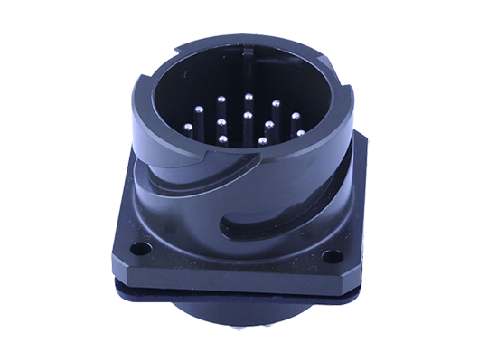
军标95234卡口航空插头
军标95234卡口航空插头
| |
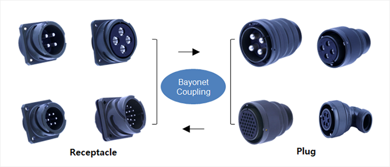
- YJ95234 Connectors
Typical Mating Guide
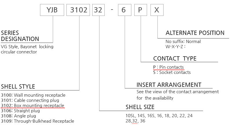
Ordering Information
Technical Data
Materials & Finish
| Materials | Finish | |
| Shell | Aluminum alloy | Olive drab chromate coating cadmium or Zinc Cadmium free surface coatings are available |
| Contact | Copper alloy | Silver plating |
| Insulation | Resilient Synthetic Rubber | |
| Grommet and seal | Silicon Rubber |
Characteristics
| Insulation resistance | Standard Insulator: 1,000MΩ, minimum (at 25ºC) |
| Temperature range | -55ºC to 125ºC |
| Durability | 500cycles connection / disconnection |
| Contact Rating | ||
| Contact Size (AWG) | Max. Rated current, (A) | Max.Contact Resistance, (mΩ) |
| 20 | 8 | 12 |
| 16 | 22 | 6 |
| 12 | 41 | 3 |
| 8 | 74 | 1 |
| 4 | 135 | 0.5 |
| 0 | 245 | 0.2 |
| Test Voltage | |
| Service rating | Test Voltage(V) |
| Inst. | 1,050 |
| A | 1,600 |
| B | 4,000 |
| D | 2,500 |
| E | 3,000 |
| Separating force per contact | Retention test force, N | ||
| Contact Size (AWG) | N | Gage (following VG 95234 part 1) | |
| 20 | 0.3 | G0.99 | 30 |
| 16 | 1 | G1.56 | 35 |
| 12 | 1.5 | G2.36 | 55 |
| 8 | 3 | G3.58 | 80 |
| 4 | 4 | G5.69 | 90 |
| 0 | 8.5 | G9.04 | 95 |
All specifications are subject to change without notice. For more information on the technical data and test methods,please contact our technical department.
Contact Arrangement
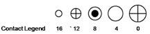
Shell Size 10
| Insert Arrangement | 10SL-3 | 10SL-4 |
| Front face of pin inserts |  |  |
| Service Rating | INST.A | A |
| Number of Contacts | 3 | 2 |
| Contact Size | 16 | 16 |
Shell Size 14
| Insert Arrangement | 14S-1 | 14S-5 | 14S-6 | 14S-12 |
| Front face of pin inserts |  |  |  |  |
| Service Rating | A | INST | INST | A |
| Number of Contacts | 3 | 5 | 6 | 3 |
| Contact Size | 16 | 16 | 16 | 16 |
Shell Size 16
| Insert Arrangement | 16S-1 | 16-10 | 16-11 | 16-12 |
| Front face of pin inserts |  |  |  |  |
| Service Rating | A | A | A | A |
| Number of Contacts | 7 | 3 | 2 | 1 |
| Contact Size | 16 | 12 | 12 | 4 |
Shell Size 18
| Insert Arrangement | 18-1 | 18-5 | 18-8 | 18-10 | ||
| Front face of pin inserts |  |  |  |  | ||
| Service Rating | B,C,F,G=A; all others=INST | D | A | A | ||
| Number of Contacts | 10 | 1 | 2 | 7 | 1 | 4 |
| Contact Size | 16 | 16 | 12 | 16 | 12 | 12 |
| Insert Arrangement | 18-11 | 18-12 | 18-19 | 18-21 |
| Front face of pin inserts |  |  |  |  |
| Service Rating | A | A | A | A |
| Number of Contacts | 5 | 6 | 10 | 3 |
| Contact Size | 12 | 16 | 16 | 12 |
Shell Size 20
| Insert Arrangement | 20-2 | 20-3 | 20-11 | 20-19 |
| Front face of pin inserts |  |  |  |  |
| Service Rating | D | D | INST | A |
| Number of Contacts | 1 | 3 | 13 | 3 |
| Contact Size | 0 | 12 | 16 | 8 |
| Insert Arrangement | 20-22 | 20-23 | 20-29 | |
| Front face of pin inserts |  |  |  | |
| Service Rating | A | A | A | |
| Number of Contacts | 3 | 3 | 2 | 17 |
| Contact Size | 16 | 8 | 8 | 16 |
Shell Size 22
| Insert Arrangement | 22-2 | 22-12 | 22-14 | |
| Front face of pin inserts |  |  |  | |
| Service Rating | D | D | A | |
| Number of Contacts | 3 | 2 | 3 | 19 |
| Contact Size | 8 | 8 | 16 | 16 |
| Insert Arrangement | 22-21 | 22-22 | 22-23 | |
| Front face of pin inserts |  |  |  | |
| Service Rating | A | A | A,B,C,D,E,F,G=A ; H=D | |
| Number of Contacts | 2 | 1 | 4 | 8 |
| Contact Size | 16 | 0 | 8 | 12 |
Shell Size 24
| Insert Arrangement | 24-9 | 24-10 | 24-11 | 24-12 | ||
| Front face of pin inserts | 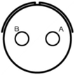 | 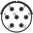 | 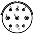 | 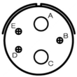 | ||
| Service Rating | A | A | A | A | ||
| Number of Contacts | 2 | 7 | 6 | 3 | 3 | 2 |
| Contact Size | 4 | 8 | 12 | 8 | 12 | 4 |
| Insert Arrangement | 24-20 | 24-22 | 24-28 | |
| Front face of pin inserts | 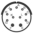 | 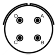 | 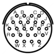 | |
| Service Rating | D | D | INST | |
| Number of Contacts | 9 | 2 | 4 | 24 |
| Contact Size | 16 | 12 | 8 | 16 |
Shell Size 28
| Insert Arrangement | 28-6 | 28-10 | 28-11 | |||
| Front face of pin inserts | 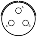 | 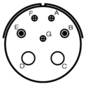 | 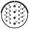 | |||
| Service Rating | D | G=D; all others=A | A | |||
| Number of Contacts | 3 | 3 | 2 | 2 | 18 | 4 |
| Contact Size | 4 | 12 | 8 | 4 | 16 | 12 |
| Insert Arrangement | 28-15 | 28-21 | 28-22 | |
| Front face of pin inserts | 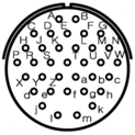 | 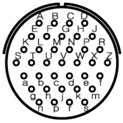 |  | |
| Service Rating | A | A | D | |
| Number of Contacts | 35 | 37 | 3 | 3 |
| Contact Size | 16 | 16 | 16 | 4 |
Shell Size 32
| Insert Arrangement | 32-1 | 32-5 | 32-7 | ||
| Front face of pin inserts |  | 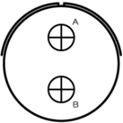 | 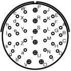 | ||
| Service Rating | A=E; all others=D | D | A,B,H,j=ISNT;; all others=A | ||
| Number of Contacts | 3 | 2 | 2 | 28 | 7 |
| Contact Size | 12 | 0 | 0 | 16 | 12 |
| Insert Arrangement | 32-15 | 32-17 | |
| Front face of pin inserts |  | 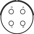 | |
| Service Rating | D | D | |
| Number of Contacts | 6 | 2 | 4 |
| Contact Size | 12 | 0 | 4 |
Shell Size 36
| Insert Arrangement | 36-3 | 36-5 | |
| Front face of pin inserts | 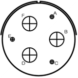 | 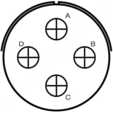 | |
| Service Rating | D | A | |
| Number of Contacts | 3 | 3 | 4 |
| Contact Size | 12 | 0 | 0 |
Other contact arrangement not listed here, Consult factory
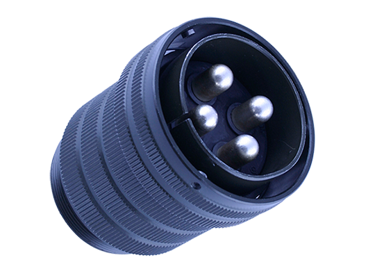
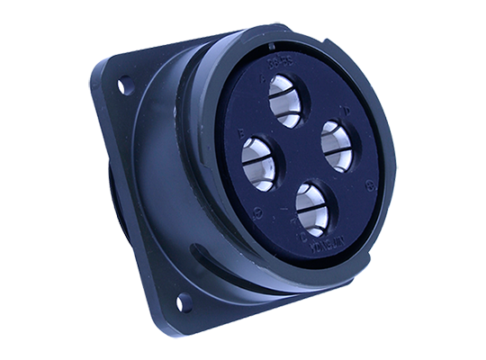
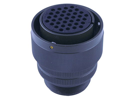
YJ 95234 Series Connector
YJ95234-Bayonet Connector is an improved version of the threaded MIL-C-5015 series, which was designed in accordance with the VG95234 specification. YJ95234 connector employs a proven bayonet coupling design that provides fast and easy connection / disconnection. The applications for this rugged connector includes the electrical equipment of tracted vehicles, heavy earth-moving equipments, ships,telecommunications and others. Connectors in accordance with VG95234 are interchangeable with the corresponding MIL-C-5015 connectors. Both connector lines feature the same shell dimensions and contacts layouts. However, due to the different coupling systems, they are not intermateable. For more information,please contact our sales depart ment.
Features
Bayonet coupling for easy mating and unmating Rugged shell design Wide selection of shell styles and contact patterns Solder contacts, silver plated copper alloy, sizes from #16 to #0 Zinc alloy plating (cadmium free) available Intermateable with existing VG95234 connectors
上一篇:军标26482系列圆形连接器
下一篇:菲尼克斯连接器介绍
版权与免责声明:凡本网注明“来源:亚洲制造网”的所有作品,均为浙江兴旺宝明通网络有限公司-亚洲制造网合法拥有版权或有权使用的作品,未经本网授权不得转载、摘编或利用其它方式使用上述作品。已经本网授权使用作品的,应在授权范围内使用,并注明“来源:亚洲制造网”。违反上述声明者,本网将追究其相关法律责任。 本网转载并注明自其它来源(非亚洲制造网)的作品,目的在于传递更多信息,并不代表本网赞同其观点或和对其真实性负责,不承担此类作品侵权行为的直接责任及连带责任。其他媒体、网站或个人从本网转载时,必须保留本网注明的作品第一来源,并自负版权等法律责任。 如涉及作品内容、版权等问题,请在作品发表之日起一周内与本网联系,否则视为放弃相关权利。
展开全部